diff options
| -rw-r--r-- | 08.-Passive-Radar.md | 16 |
1 files changed, 9 insertions, 7 deletions
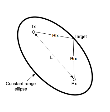
diff --git a/08.-Passive-Radar.md b/08.-Passive-Radar.md index 3396556..492f195 100644 --- a/08.-Passive-Radar.md +++ b/08.-Passive-Radar.md @@ -84,11 +84,11 @@ If you are using DAB (or other more narrow illuminators), note that this only ha # Range-Doppler Units The range-doppler graph displays bistatic range and bistatic speed. The axes are currently described in CELLS. In order to convert cells to meters or m/s use the following formulas: -$Bistatic Range (meters) = cell * c/fs$ +$Bistatic Range (meters) = R_b = cell * c/fs$ Where $c$ is the speed of light, and $fs$ is the sample rate (aka bandwidth), and $cell$ is the x-axis cell. The sample rate by default is set to 2.4 MHz. If you have an illumination signal that is smaller, you should set your sample rate to the closest possible bandwidth that matches that illumination signal. -So for example if we see an object at cell 50 on the x-axis, and we have a sample rate of 2.4 MHz we can calculate $Bistatic Range (meters) = 50 * 299792458 / 2400000 = 15,614m = 15.6 km$ +So for example if we see an object at cell 50 on the x-axis, and we have a sample rate of 2.4 MHz we can calculate $Bistatic Range (meters) = R_b = 50 * 299792458 / 2400000 = 15,614m = 15.6 km$ For converting doppler cells to Hertz the formula is as follows: @@ -98,15 +98,17 @@ Where $fs$ is the sampling frequency as before, $N$ is the sample size of the co In the passive radar software we provide three configuration files `pr_2ch_2pow20`, `pr_2ch_2pow21`, `pr_2ch_2pow22`. In these files the difference is in the CPI value, which is set to $2^{20}$, $2^{21}$ and $2^{22}$ respectively. -Example cell 100, sampling rate 2.4 MHz and $N = 2^{22}$ +Example cell 500, sampling rate 2.4 MHz and $N = 2^{22}$ -$Bistatic Frequency (Hz) = 500 * 2400000 / (2*2^{22}) = 143 Hz$ +$Bistatic Frequency (Hz) = f_b = 500 * 2400000 / (2*2^{22}) = 143 Hz$ -Then to get to speed in m/s we simply multiple the doppler frequency with the wavelength of the illuminator, and multiply by -1. (Positive Doppler decreases the range between you and the target so it has negative speed, it is approaching) +Then to get to speed in m/s we simply multiple the Bistatic Frequency f_b with the wavelength of the illuminator, and multiply by -1. (Positive Doppler decreases the range between you and the target so it has negative speed, it is approaching) So if we were using 560 MHz as our illuminator: -$Bistatic Speed (m/s) = c / f * -doppler_freq = 299792458 / 560000000 * -143 = 76.5m/s = 275 km/h$ +$Bistatic Speed (m/s) = c / f * -f_b = 299792458 / 560000000 * -143 = 76.5m/s = 275 km/h$ + +It is noted what with increased CPI you receive the benefit of great bistatic doppler resolution, however range resolution is not increased. Increase CPI does still have the advantages of more processing gain, resulting in weaker reflections being detected. # Bistatic Range The graph provided is a bi-static range doppler graph. Bi-static means that the measurement consists of a transmitter and receiver separated by some distance. This can get complicated, as instead of getting a simple range distance value from the receiver, we end up with an ‘constant range ellipse’ of possible range solutions that depend on some calculations based on the transmitter and receiver positions. @@ -115,7 +117,7 @@ In the future we aim to have software enhancements that make understanding and v  -The bistatic range displayed on the KrakenSDR range-doppler graph is described by the formula $Bistatic range (meters) = Rtx + Rrx - L$. So you can see that a single reading on the range-doppler graph describes an ellipse of possible locations. +The bistatic range displayed on the KrakenSDR range-doppler graph is described by the formula $Bistatic Range (meters) = R_b = Rtx + Rrx - L$. So you can see that a single reading on the range-doppler graph describes an ellipse of possible locations. # Range Resolution Range resolution depends on the sampling bandwidth, which for the KrakenSDR and RTL-SDR tuners inside is 2.4 MHz. Therefore we achieve $c / fs = 299 792 458 / 2400000 = ~125m$ resolution per range cell on the graph (assuming the illuminating signal is at least 2.4 MHz as well). |
